Build Process
Overall dimension will be 24" wide, using 3/4" plywood (making inside measurement 22.5" wide), and a total length of 6 feet (so both the main box and the brain box combined will fit into a pickup truck).
The height of the sides will be dependent on the with of a 4'x 8' sheet of plywood, maybe just under 12" (to account for blade with cuts).
I will build the brain box first to see what the total depth will be then can build the main box to accomodate the 6' length.
The printed parts (Drop holes, side/top humps) will be 22.5" wide, so you might want to cut the box side/cross supports to be just a little bigger for flexibility.
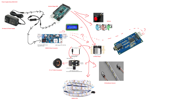
Test the Electronics
The Game Code for testing the hardware can be found at: Game Code page.

5. Attach the LED strip Data pin to #12.
6. Attach the IR Breakbeam Sensors and test they work.

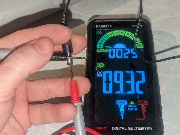
Wall Power
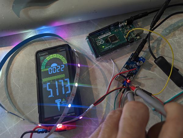
1. Test/verify the Wall Power Supply is outputting the correct voltage.
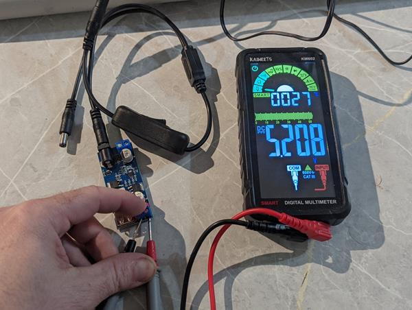
Buck Converter
2. Test the Buck Converter plugged directly into the wall, no Y splitter.
Buck Converter
3. Test the Buck Converter attached to Y split without Arduino Mega plugged in.
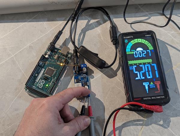
Buck Converter
4. Test the Buck Converter attached to Y split with Arduino Mega plugged in.
LED
5. Attach the LED strip Data pin to #12.
Hook the Power/Ground to the Wall/Buck Converter.
Run the test code.
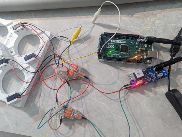
IR Breakbeam Sensor
6. Attach the IR Breakbeam Sensors and test they work.
Hook the Power/Ground to the Wall/Buck Converter.
You can connect 2 at first to verify it works, then hook up 25 and run the test code.
Note if you hook up the USB-B connector, the TX light on the board will flash when breaking the beam. On the DC Barrel jack, you have to use the onboard LED.
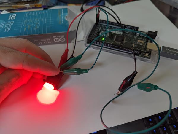
Buttons
7. Notice there are two Positives and two Negatives. One set is for LED, other for signal. The LED negative needs a 1k resistor. LED Positive: p48, Button Positive: p48 for one button testing.
Note: The grounds need to be on separate ground circuits.
LCD
8. LCD
Music
9. Music player, DF Mini, PAM8406, Speakers
BrainBox
Next is to build the Brain Box.
Brain Box
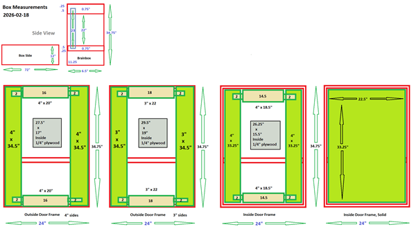
Brainbox Frame
Brainbox frame to house the Arduino, Buck Converter, Wall Power Plugin, etc.
more text
-
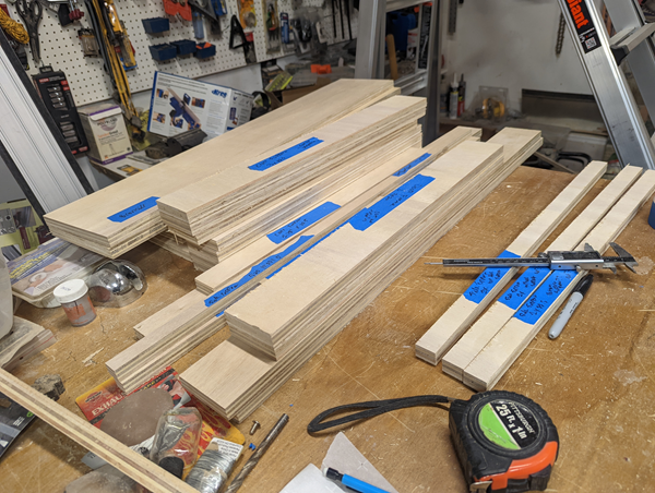
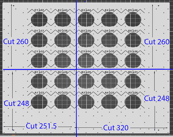
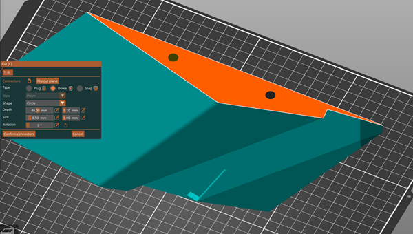
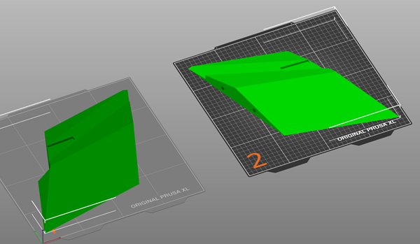
Cut out all the pieces using the cut template. The width is 6.5" by XXX (fix the length to match 11.75" frame height)
-
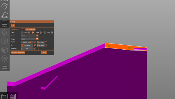
Add a cutout for the mirror slot, 0.5" in from the edge and 0.5" deep.
NOTE: Try cutting LESS THAN 0.5" then go deeper as needed to accomodate non-perfect cuts.
.png)
.png)
.png)
-
Cut pocket holes, at least 1" from edge. Added extra for clearing Slot and stil be able to use a drill.
.png)
.png)
-
Square the frame, screw the ends to make the box. Use glue on the base and middle (if wanting) but not on the top so you can unscrew and remove the mirror.
Attach using 1-1/4" pocket screws, made for 3/4" Plywood.
Attach the middle support so the bottom of the wood is 24" down from the top. Also note the middle support shelf is 5.75" wide so make sure it's screwed flush to the outside.
NOTE: Don't screw in the middle support shelf until the Acrylic Mirror is slide in from the top. It "SHOULD" be 24" but the 3/4" Plywood isn't really 3/4".
.png)
.png)
Marked.png)
-
Slide the Acrylic Sheet in to verify it fits. Mine was cut wrong, add real picture after assembly.

-
Cut pocket holes into the sides of the front cover and screw in. You can also use glue/adhesive on the sides/bottom as this will be bolted to the main frame.

Main Box Frame Build
Box Frame
Outside Frame
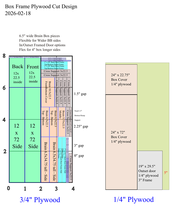
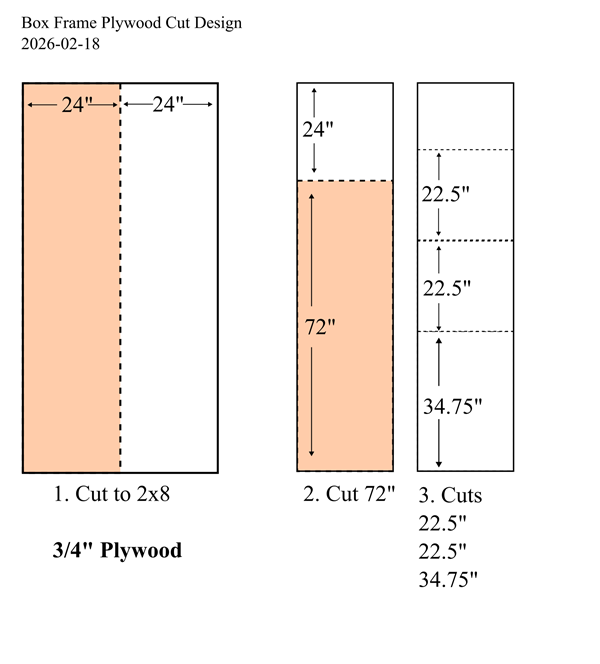
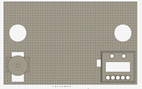
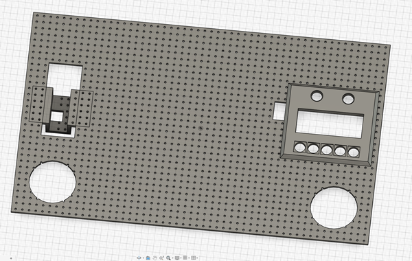
The main box can be cut out of one sheet of 4x8 plywood using the image for reference.
Note the 22.5" side supports CANNOT be cut less or the printed parts will not fit. You could add an 1/8th or something for just in case.
I created a 2.5" spacer tool, this will be the distance from the top frame to the cross supports.
All the humps are around 1.5" tall (+14mm for drop holes) which is 1.55" total height so this 2.5" spacer gives 1" clearance at the top.
This tool also has a 1" spacer which can be used for a gap between the side and cross supports.
This stops normal rolling balls from going over the side, maximizes clearance below the drop holes to the down ramp, and allows a cover to be put on the top.
-
Cut out all the pieces using the cut template. Make the height of the frame 11.75".
-
Cut pocket holes in the top/bottom 22.5" x 11.75" ends. 4 or 5? make sure to stay 1" in from the edge.
-
Square the frame, screw the ends to make the box. Can use Construction Adhesive or wood glue for extra strength.
Thinking about making the ball slot front piece shorter, need to test.
- Cut 2 pocket holes per side in all the Cross Supports.
- Use (2) of the 3" Cross Supports and attach to the bottom layer at the top/bottom for strength.
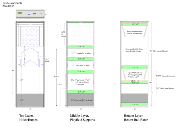
- Use (1) 3" Cross Support for the Ball Opening, measuring up 10.5" from the inside and 2.5" from the top (use spacer). Attach using the 1-1/4" Kreg Pocket Screws.
- Measure 14" up for the Undermount. Measure with actual print to verify distance. Attach another 3" cross support.
-
Attach a side support XX" x 1"? between the two cross supports above. Leave 1" gap on both sides.
Use #8 x 1 - 1/4" Spax Screws.
- xxx
- xxx
- xxx
- xxx
- xxx
- xxx
- xxx
3D Prints
Be sure to print up the Test Pieces to verify Threaded Rods and other items fit properly. Most connecting holes are 4.5mm to fit a threaded rod or 8.5mm to fit a fiberglass rod.
For V3, I'm going to try using Pro PLA+ for printing to help minimize warping for large prints.
For the Drop Holes, print upside down so the playing surface is smooth
I think I will upload all these printed parts to Printables.com when finished.
Total Printing Time: 144 hours and 02 minutes
Total Filament Used: 4772 g
3D Printing Material Table
| Part | Filament | Time |
|---|---|---|
| Brainbox Template | 718 g | 18 hr 58 min |
| Buttons/LCD | 54 g | 2 hr 13 min |
| Down Ramp | 484 g | 13 hr 16 min |
| Drop Holes | 1313 g | 40 hr 39 min |
| Drop Holes Side Humps | 709 g | 16 hr 49 min |
| Frame Template | 241 g (88 g for 4" wide) | 5 hr 9 min (1 hr 54 min for 4" wide) |
| IR Sensor Case | 166 g | 12 hr 22 min |
| Main Hump / Side Block | 560 g | 14 hr 4 min |
| Playfield Electronics Undermount | 456 g | 17 hr 59 min |
| Speaker Hole Cutout Template | 5 g | 9 min |
| Volume Amplifier | 66 g | 2 hr 24 min |
Reference table for Threaded/Fiberglass rods to cut.
| Part | Material | Cut Length | Quantity |
|---|---|---|---|
| Downramp | #8 Threaded Rod | 160 mm (6.3") | 2 pieces |
| Drop Holes | #8 Threaded Rod | 50 mm | (22 total) 15 pieces for gluing, 7 to connect to Down Ramp |
| Drop Holes Side Humps | Fiberglass Rod | 80 mm | 3 pieces |
| Main Hump | Fiberglass Rod | 80 mm | 2 pieces |
Fiberglass: 400mm (15.75")
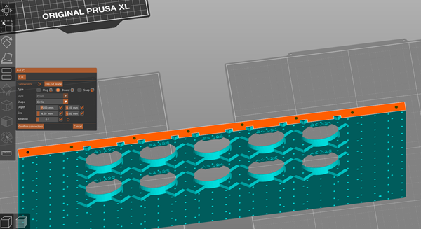
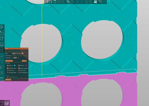
Marking Templates
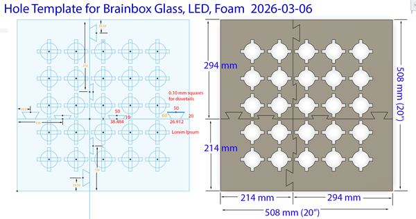

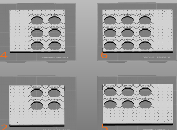
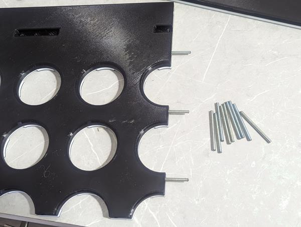
Brain Box LED, Mirror, and Foam Marking Template
Filament Type: Pro PLA+
Filament Used: 717.76 g (Spray Template (1): 5.76 g, Top Left: 185 g, Top Right: 220 g, Bottom Left: 131 g, Bottom Right: 176 g)
Print Time: 18 hr 58 min (Spray Template (1): 19 min, Top Left: 4 hr 42 min, Top Right: 6 hr 2 min, Bottom Left: 3 hr 6 min, Bottom Right: 4 h 49 min)
Nozzle: 0.6 Obx
Layer Height: 0.32 Quality
Bed Temp: 60
Brim: 10
Support: None
Infill: 10%, Rectilinear
Walls: 2
This template will be used to mark the location on the board where to install the LEDs, marking the acrylic sheet for the 'mirror' layout, and where to cut holes in the foam.
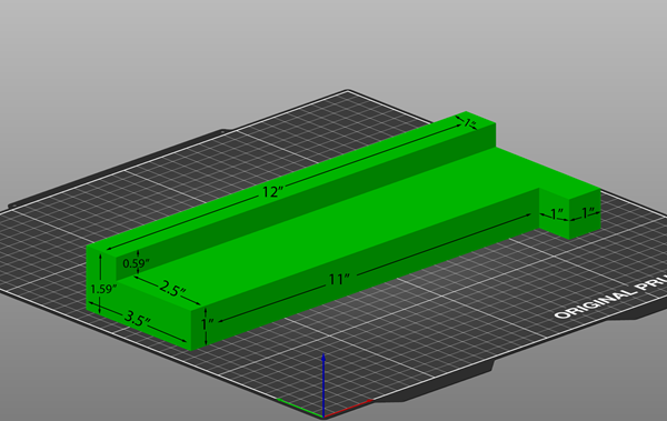
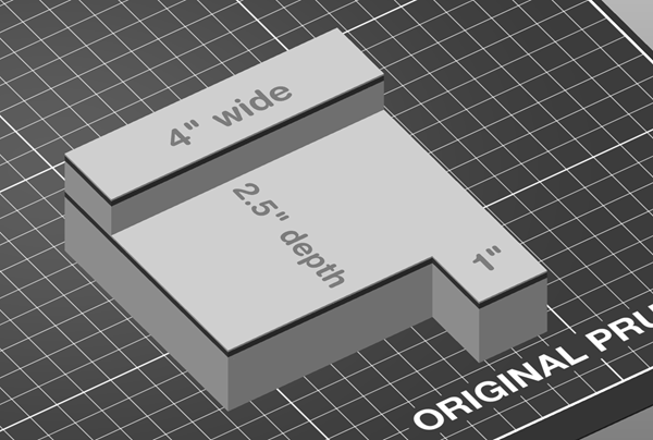

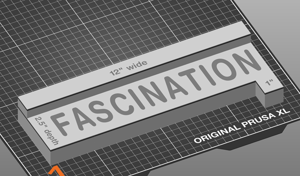
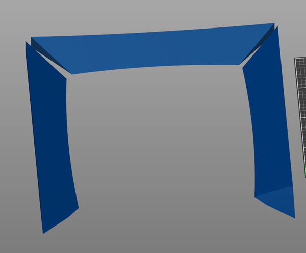
Frame Spacer Template
Filament Type: Pro PLA+
Filament Used: 241 g (88 g for 4" wide)
Print Time: 5 hr 9 min (1 hr 54 min for 4" wide)
Nozzle: 0.6 Obx
Layer Height: 0.40 Draft
Bed Temp: 60
Brim: 5
Support: None
Infill: 10%, Cubic
Walls: 2
This template will be used to mark the location of installing the Side/Cross support members from the top of the frame. It will create a 2.5" gap.
You have the option of printing the 12" wide (better, more precise measuring wider supports) or the 4" wide (to save printing time, filament, time).
.png)
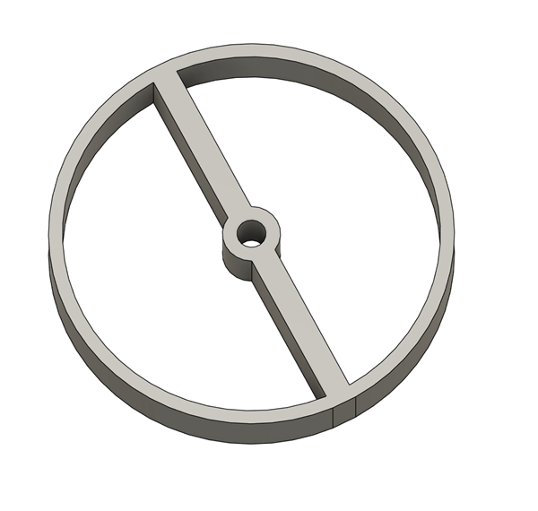
Speaker Center Hole for 3" Cutout
Filament Type: Pro PLA+
Filament Used: 5 g
Print Time: 9 min
Nozzle: 0.6 Obx
Layer Height: 0.32 Quality
Bed Temp: 60
Brim: 5
Support: None
Infill: 10%, Cubic
Walls: 2
This template will be used to mark the center location for the speaker cutout.
Drill from the bottom for the pilot hole, then drill from the top.
Buttons/LCD
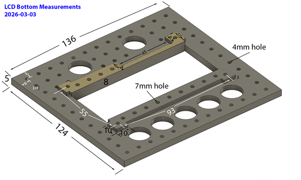
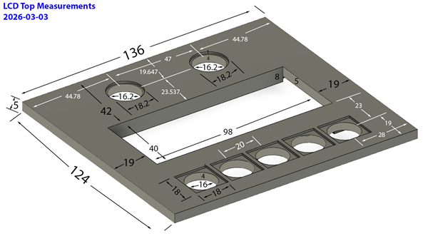
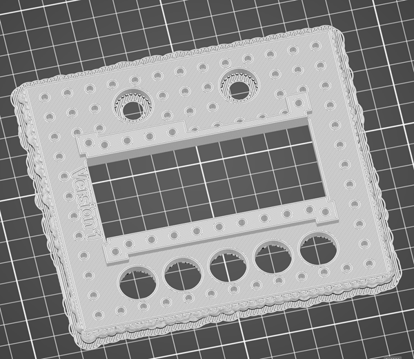
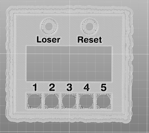
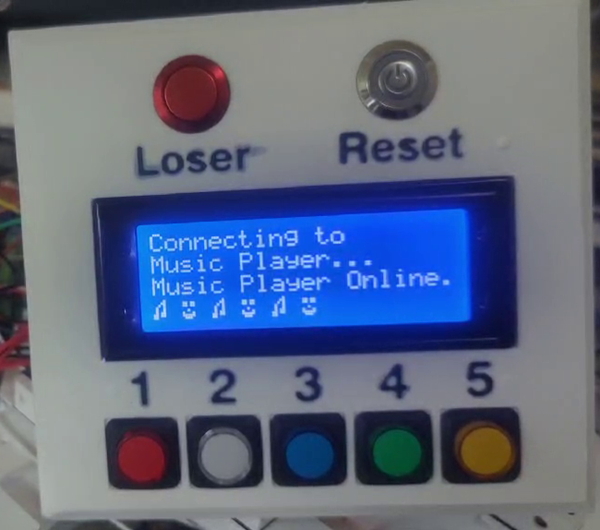
Buttons/LCD
Filament Type: Pro PLA+
Filament Used: 54 g (Dual Nozzle Color)
Print Time: 2 hr 13 min
Nozzle: 0.6 Obx
Layer Height: 0.32 Quality
Bed Temp: 60
Brim: 0
Support: Everywhere (printed upside down)
Infill: 10%, Gyroid
Walls: 2
Printing upside down so the text can be on nozzle 2. This will also let you use different sheets for texture or pattern.
Added a 5mm chamfer on the sides.
Down Ramp


Down Ramp
Filament Type: Pro PLA+
Filament Used: 484 g (242 g each)
Print Time: 13 hr 16 min (6 hr 38 min each)
Nozzle: 0.6 Obx
Layer Height: 0.32 Quality
Bed Temp: 60
Brim: 10
Support: None
Infill: 10%, Gyroid
Walls: 2
The downramp has 4mm filleted outside corners for printing.
The lower corners are covered by the side hole ramps.
The front will slide onto threaded rods connected to the Drop Holes
The gluing edge will slide into (2) 160mm threaded rods.
There are also 2.9mm holes on the bottom where you can print a spacer.
Rectangular slots for inserting 60x10x3 mm magnets, verify polarity in main hump.
The design supports a 7mm floor plank.
Cut down the center, add (2) 4.5mm holes, 80mm (6.3") (for 160mm hole) deep on each side.
Glue together with Epoxy. Can add metal hot staples to back for extra strength.
You could try using the 7mm spacer if the flooring isn't the right size and move it back from the down holes.
Drop Holes


Drop Holes
Filament Type: Pro PLA+
Filament Used: 1313 g (TopLeft: 375 g, TopRight: 391g, BottomLeft: 271g, BottomRight: 276g)
Print Time: 40 hr 39 min (TopLeft: 11h43m, TopRight: 12h14m, BottomLeft: 8h14m, BottomRight: 8h28m)
Nozzle: 0.6 Obx
Layer Height: 0.32 Quality
Bed Temp: 60
Brim: 15
Support: Build Plate Only
Infill: 10%, Gyroid
Walls: 2
Droholes has a 20x20 grid hole bottom for attaching clips for wires and other items. They are 11.2mm deep. Do NOT use a screw longer than the hole, it'll buldge the top.
Print with the cutouts NOT THROUGH the holes. I tested with hole cuts its not as perfect.
Multi color .3mf setup for Black on top with black lettering and white underside.
You will need (15) 50mm pieces of #8-32 threaded rod for gluing together.
You will need (7) 50mm pieces of #8-32 threaded rod for connecting to Down Ramp.
Thread Rod total: 1100mm (43")
Use BSI Epoxy, gluing 2 sections together, then slide for final two together.


Drop Holes Side Humps
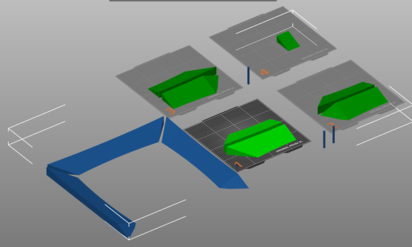
Drop Holes Side Humps
Filament Type: Pro PLA+
Filament Used: 709 g (Top: 245 g, Left: 232 g, Right: 232 g)
Print Time: 16 hr 49 min (Top: 5h43m, Left: 5h32m, Right: 5h34m)
Nozzle: 0.6 Obx
Layer Height: 0.32 Quality
Bed Temp: 60
Brim: 10
Support: Yes
Infill: 10%, Gyroid
Walls: 2
Use Fiberglass rods to fill the 8.5mm hole.
Cut to 80mm (really 78mm) long and sand off the smooth exterior.
Support Enforcers Only on corner pieces, leaving cut out holes no supports.
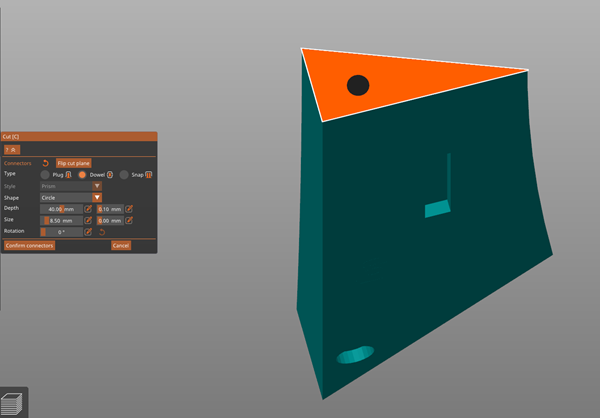
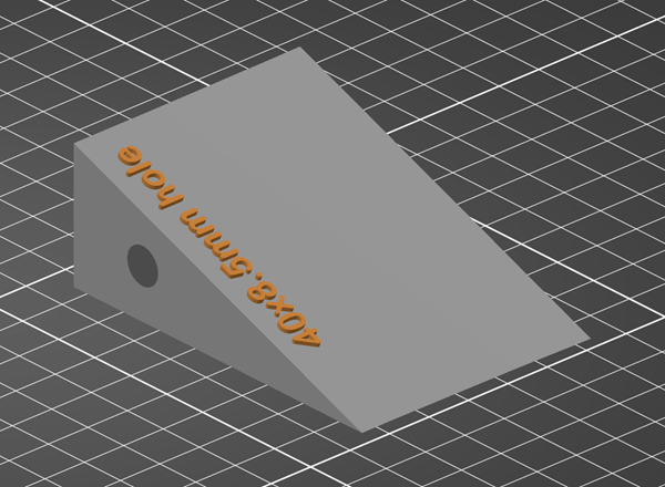
Print test block for 8.5mm hole for fiberglass rod
.png)
.png)
.png)
IR Sensor Case
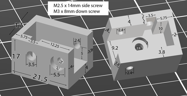
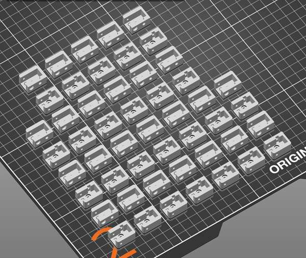
IR Sensor Case
Filament Type: Pro PLA+
Filament Used: 166 g (6.88 g each set)
Print Time: 12 hr 22 min (31 min for 1 set)
Nozzle: 0.6 Obx
Layer Height: 0.20 detail
Bed Temp: 60
Brim: None
Support: None
Infill: 20%, Cubic
Walls: 2
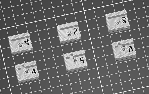
You'll need 25 sets (1 Left, 1 Right).
I kept three heights, 4mm, 5mm, and 8mm.
The "height" is the depth of the base the sensor sits in.
Drop holes have a 5mm cut out so using the 5mm base will put the laser level w/ the bottom of the drop holes.
4mm will drop 1mm which is max with the wires sticking out.
If you want 6mm, then take the 8mm and cut 2mm off the bottom.
I'm using 5mm base so the IR sensor sits flush.
I also added a 2nd color to fill in the number designating the height.
Main Hump / Side Block
Main Hump / Side Block
Filament Type: Pro PLA+
Filament Used: 560 g (280 g each side)
Print Time: 14 hr 4 min (7h2m)
Nozzle: 0.6 Obx
Layer Height: 0.32 Quality
Bed Temp: 60
Brim: 10
Support: No
Infill: 10%, Gyroidxxx
Walls: 2
Cut in half, use 8.5x40mm hole cut outs for (2) 80mm fiberglass rods and sand off the smooth exterior.
Playfield Electronics Undermount
Playfield Electronics undermount
Filament Type: Pro PLA+
Filament Used: 456 g (Left: 244 g, Right: 212 g)
Print Time: 17 hr 59 min (Left: 9 hr 38 min, Right: 8 hr 21 min)
Nozzle: 0.6 Obx
Layer Height: 0.32 Quality
Bed Temp: 60
Brim: 10
Support: No
Infill: 10%, Rectilinear
Walls: 2
This can be printed with speakers on Top or Bottom. Originally I did on bottom but thinking of moving speakers to top so the buttons/volume is easier to use.
Also the rolling ball lines will be a little more since the LCD is less in the way.
Also, the Volume Knob has the ability to be moved up and down for personal preference... but locked in place once you cut the playfield for installation.
Volume Amplifier

.png)
.png)
.png)
.png)
.png)
.png)
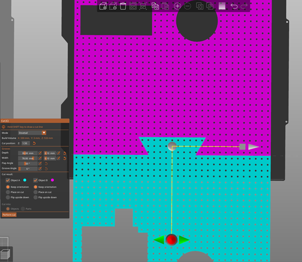
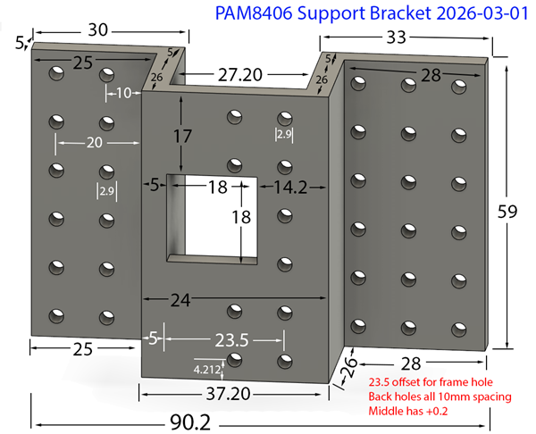
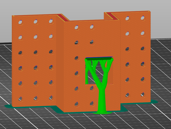
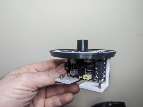
PAM8406 Frame, Suppport Bracket, and Cover
Filament Type: Pro PLA+
Filament Used: 66 g (Support Bracket: 35 g, Support Frame: 11 g, Cover (80mm): 20 g)
Print Time: 2 hr 24 min (Support Bracket: 1 hr 11 min, Support Frame: 33 min, Cover: 40 min)
Nozzle: 0.6 Obx
Layer Height: 0.32 Quality
Bed Temp: 60
Brim: 10
Support: Support Enforcers
Infill: 10%, Gyroid
Walls: 2
Pam FRAME is what the unit will screw into.
Pam Bracket will be screwed to the undermount and the frame will slide into it.
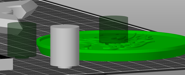
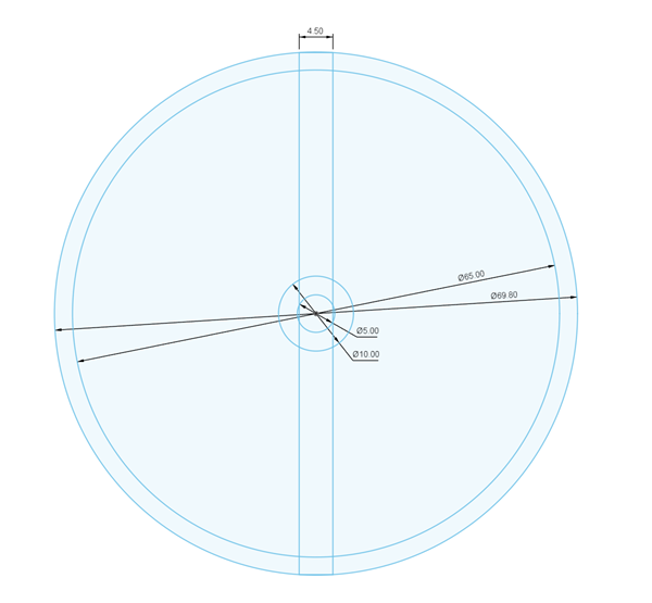
The cover (coaster) can be anything, I resized to 80mm (could be wider) and 5 mm tall (to match the LCD).
The cover has a negative stl you can place into it for the knob cutout. The knob will sit below the surface.
The undermount cutout will allow you to 'move' the unit up/down pending preference.


xxx
xxx
Filament Type: Pro PLA+
Filament Used: xxx g (xxx g each set)
Print Time: xxx hr xxx min (xxx min)
Nozzle: 0.6 Obx
Layer Height: 0.xxx detail
Bed Temp: 60
Brim: xxx
Support: xxx
Infill: xxx%, xxx
Walls: 2
xxx
xxx
Playfield Top
Electronics area
.png)
.png)
.png)
.png)
Speaker Holes
Use the center template to find the center hole then drill a 3" hole.
xxx